Transformations
Groups are used to position, scale and rotate subtrees in arbitrary ways. This feature is one of the main reasons why scene graphs exist. It allows combining, repeating and modifying any visual object to form more complex new objects. The principle should get clear when walking through the examples in this section.
We start with some basic exploration of coordinate systems. Users already familiar with the topic from other 3D engines or 3D computer graphics in general may skip over this section.
A coordinate system can be seen as a scale how to interprete positions and distances of objects contained in the coord system. If no coordinate system was defined, a position of (0, 1, 0) for a vertex wouldn’t make too much sense. It is the coordinate system which defines – let’s say: „My origin lays at the center of the scene, the X direction goes to the right, Y goes up and Z comes out of the screen.“ This is what gives (0, 1, 0) a meaning. It helps us to map coordinate tuples for X, Y and Z directions to imaginary positions in the world.
Per default, users of ILNumerics scene graphs can choose from two predefined coordinate systems:
- A screen coordinate system places the origin (0, 0, 0) at the upper left corner of the rendering surface (the controls client area). (1, 1, 0) corresponds to the lower, right corner. So, a point at (0.5, 0.5, 0) would appear at the center of the render surface. If you are wondering what the third (Z) coordinate is about – let’s put that aside for now. Screen basically is for 2D objects. The screen coordinate system of any scene is accessed by ILScene.Screen.
- A world coordinate system provides access to a 3D coordinate system. Its origin lays at the center of the ‚world‘ – an imaginary space which is used to relate object positions and distances. The positive X direction goes to the right, positive Y direction goes up and the positive Z direction comes out of the screen. Commonly, 2D screens are used to watch the 3D world eventually. Therefore, a camera is used for projecting it to a flat display. Now, in ILNumerics the terminology would better be: the world is defined by the camera. If you start up a new scene, the 3D world comes with a predefined camera. It is positioned at (0, 0, 10) and looks at the center of the scene. The 3D world coordinate system is accessed by ILScene.Camera.
The main task for group nodes is not only to contain children and hence build up the scene tree. Group nodes are responsible for providing coordinate systems. Or even better stated: groups convert between coordinate systems.
An example: We create a scene with only a single triangle.
The triangle was created with default values and placed directly into the Scene.Camera node of our panel.
Now, we create another triangle. Let’s assume that the goal would be to create some sort of fractal. The second triangle should be located within the first one.
Note how we must set the Z coordinate of the new triangle at some small value to make the new triangle appear on top of the first one.
In order to create something more interesting, we could follow that approach, i.e., create two more triangles and derive its vertices from the positions of the existing ones and so on. But in the next step, we already have to create 4 triangles … it is obvious, we need another approach.
Group nodes are here to group things together. Our world camera node is a group, which groups all children contained within. We can easily create our own groups and use them to organize useful subtree parts together. In the following we create the same figure as before, except this time we only use wireframes and only the replication and transform capabilities of groups.
We start from scratch:
This produces an equilateral triangle as wireframe. This time, we have created the triangle as child of a new group node. Until now, nothing has changed, since the group does not change any coordinate system by default.
We took the group with the triangle and added it to itself again! What is this for? Adding a node to a group in ILNumerics scene graphs will simply add the node to the children's collection of the group. So now, our group should contain the following (hovering over group1 in VS):
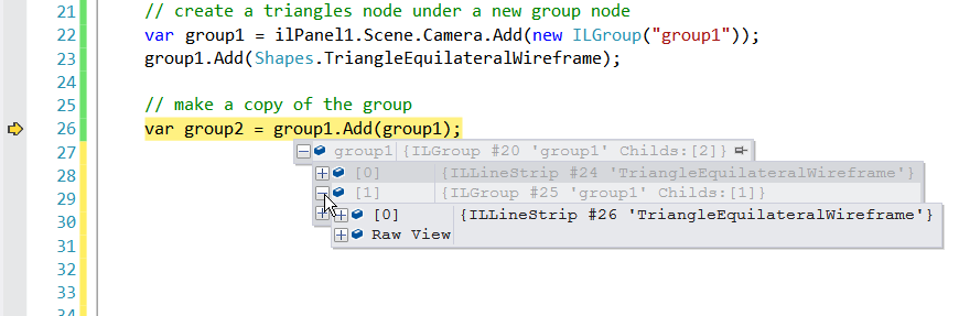
Exactly spoken, we did not only add the node to itself, since this would introduce circular references which often cause trouble. ILNumerics rather automatically creates a clone of the original node, if the node is already used somewhere in the tree. If the original is a group node, the clone will represent the entire subtree. This can also be seen by the #IDs of the nodes within the group1 subtree – they are all unique (See: Buffers) to learn more about cloning scene graph nodes).
Since we actually add a clone of group1, we save the return value into a new group2 variable.
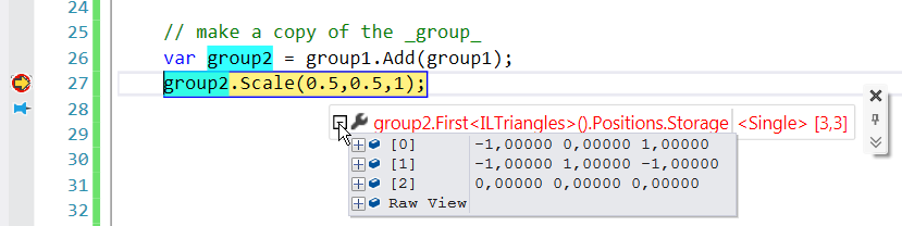
Even if not visible – from the result – our scene now contains two triangles. Both lay exactly on top of each other. So let’s fix this by scaling the second groups content down:
We use the Scale function of the returned group to scale down everything inside of it. The group creates a new coordinate system: It has the same origin (at the center of the world) but coordinate values of 1 will appear as 0.5 for X and Y directions. The Z direction remains unchanged.
The triangle contained in group2 still has the same vertex positions:
However, since group2 scales the vertex positions of the triangle for rendering, the triangle now appears smaller in the output. We still need to move the triangle to the lower left corner:
In addition to the scale configuration of group2, we apply a translation to the group. Both transforms are combined! Now group2 will not only scale all its child nodes down in X and Y direction, it will also move them by some amount in X and Y direction.
The result is similar as for the filled triangles before. But this time, we didn’t have to configure ANY vertices! For larger scenes, not only the effort for configuration is saved. Moreover, the scene graph is able to save a lot of memory by reusing the (unmodified) vertex buffers.
Accumulating Transforms
Arbitrary numbers of Affine Transformations can be ‘stored’ into a group node. All transforms are captured, accumulated and applied to the child tree for rendering. In the last example we accumulated two transforms into a group node: scale and translation. In addition to that, rotations are possible as well.
ILGroup provides the following methods for transforms:
It must be noted that the order of such transforms is important. Rotating a translated cube is much different from translating a rotated cube: Rotations are always done around the coordinate system origin. Similarly, if a scale was applied to a group, subsequent translation must take the existing scale into account.
The order of transforms applied to a group is important. New transforms are accumulated by taking existing transformations into account.
The accumulation is done by storing all transforms into a single 4x4 matrix. The details of the underlying algebra are well known but out of focus of this guide. The Transform property allows the access and direct configuration of all accumulated transforms. The property can be used to apply a number of transforms directly:
The transforms are applied in the order of appearance. First a translation, then a rotation around the Z axis; afterwards the inverse translation and a doubling of the size (scaled by 2). Accumulated transforms therefore can be stored into Matrix4 variables and reused.
Transform can also be used to reset the group to initial state, i.e.: no transformation:
This will delete all transforms currently applied to the group.
Properties, Overrides
ILGroup provides a number of properties which can be used to control the corresponding settings of the whole subtree:
| Property | Values | Default | |
| Transparency / Alpha | .Alpha | 0f (transparent … 1f (opaque) | null | null |
| Color | .Color | System.Color | null | null |
| Visibility | .Visible | true / false | True |
| Transform | .Transform | [Matrix4] | Matrix4.Identity |
When any of these properties are set explicitely, they will override the corrensponding property of any node in the subtree below. The alpha property of ILGroup, e.g. is useful for blend in/out effects. Setting .Alpha to a value other then null will make the whole subtree appear transparent.
Setting Color to any System.Drawing.Color colors all objects in the subtree in that color. Similarly, setting Visible to false hides all objects in the subtree.
Further Reading
The examples in this section are continued and expanded in the next section: Duplicating Subscenes