Using Light
Lighting often enhances three dimensional scenes for a better overview and more realistic impressions.
Litable Objects
ILNumerics Visualization Engine does not distinguish between `lit objects` and `unlit objects`. All basic shapes that create an area, which potentially could reflect light are `litable`. Those objects are: Triangles, TrianglesFan and TrianglesStrip. Lines and Points are not litable.
If an object is lit or not, solely depends on the existence of normal vectors for the shape. Normal vectors are stored in the Normals buffer for the shape. If at time of rendering sufficient normals are found in the normals vector, the shape will be rendered as lit shape. Otherwise, the shape will be rendered without light.
 Types of Lights
As common for any rendering engine, four types of light influence the lit experience for lit objects:
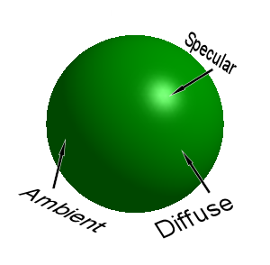
- Ambient light is the light which will always be there in a scene, regardless of any real light shining on the object. This is to prevent from (often unwanted) complete darkness for unlit scene parts. Ambient light is like the background radiation of the universe, but ... well, you'll see the difference.
- Diffuse light takes real lights into account. It produces lighter colors on those areas of lit objects, which are oriented towards the light. Triangles, which are oriented away from the light do not receive any diffuse ligthing at all. All angles in between are interpolated.
- Specular light is only visible, if the lit area is oriented in such way that the camera could 'see' the light directly reflecting in the area - very similar to a mirror. Since light objects in ILNumerics do not have a size, the specular reflection is configurable in various ways in order to simulate a real light. Shape.SpecularColor and Shape.Shininess are used in order to control the color and the shape of specular reflections.
- In addition to light falling onto the shape, there is Emissive light, which is used to simulate 'glow'. Consequently, Shape.EmissionColor is a property of the shape. It determines the color and hence the intensity of the glowing effect. Note, that emissive light exposes some similarities with ambient light, but it is configured for each shape individually, while ambient light is a property of the scene.
The final result is produced by individually computing all light components and adding them up. In order to read more about the general functioning of lights and the internals of light computations, visit the OpenGL official specification and/or the lighting articles on glprogramming.com.
Programming Lights
Currently, there is only one light object in ILNumerics Visualization Engine: PointLight. Point lights simulate a common light source like a bulb or the sun. Such lights have a position, a color and an intensity. However, they do not have an extent, hence, they are considered to be infinitesimal small points.
Lights in ILNumerics Visualization Engine act like regular scene objects. They derive from Node, are placed in group nodes and transformed by their common translation and rotation properties. For interactive or dynamic scenes, the placement of the light determines whether the light is going to move with the objects or stays stationary.
If you want the light to move with the object, just place the light into the same group node as the object. For global lights, enabling the objects to be rotated and shined on from all sides – place the lights outside of the camera node responsible for rotation.
Normal Vectors
For lighting to work correctly, every lit vertex needs an indication of the orientation of its surface normal. In order to find this orientation, a normal vector for every vertex is used. Normal vectors can be created automatically in most situations.The normals for each vertex are created by taking the normal vectors of all faces sharing that vertex into account and averaging over their orientations. Automatic normals are created for all triangle shapes, if the Shape.AutoNormals property is true (default).
If needed, the user can manually compute normals and provide them to the Shape.Normals buffer. AutoNormals should be set to false in that case, in order to prevent from automatically overriding custom normals on updates to the shape. The format of the normals buffer is similar to the format of the Positions buffer: Each vertex is represented by a column in a 3 x n matrix, where n is the number of vertices used in the shape.
Global Illumination
All lights in a scene are global. This means, regardless of the scene node a light was placed into, it will affect all visible objects. The intensity of a color caused by a light directly corresponds to the distance of the light from the shape (recall that all lights in ILNumerics Visualization Engine by now are point lights), and from the intensity of the light. In order to simplify the setup of a lit scene, ILNumerics Visualization Engine implements a relative intensity lighting model. There is no absolute value for the light intensity. Rather the intensities of all lights will be taken into account and the rendering result will reflect the configuration of relative intensities. Lights with a high value for Light.Intensity will get more influence on the final color of a shape than those with lower intensity.
Default Light Setup
ILNumerics creates a single light for each scene by default. The light is placed in a separate group node with the tag "".
Basic Lighting Example
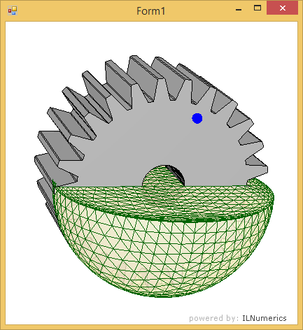
The following example demonstrates various features in conjunction with lit scenes. It creates a simple scene consisting out of a gray gear shape and a gray, transparent hemisphere. The hemisphere is configured with a nice yellow emission color. A blue light is added to the default light of the scene. The user can drag the blue light around with the mouse in order to learn the various effects of the positioning. Double clicking on the blue light (actually on the blue point shape marking the light position, since all lights are invisible) will toogle the light on and off.
Basic Lighting Example - Blue Light OFF
Basic Lighting Example - Blue Light ON
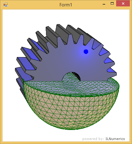
The example demonstrates the influence of the distance of lights to shapes and the effect of global illumination: the overall scene light is greatly dimmed by switching on the additional blue light.
It is also clearly visible from the example that the lighting scheme will not always create the same visual result one might expect from real-world experiences. ILNumerics Visualization Engine focuses on a simple setup rather than reaching for foto-realistic scenes. For latter, additional features would be needed: shadows and textures being only two of them. However, for most technical scenes, the simple lighting model brings the advantage of fewer / no configuration necessary for creating a good sense of 3D geometry and great performance for complex scenes.