Scene Graph Overview
All visual controls in ILNumerics use a scene graph structure to define the content to be displayed.
A scene graph is a tree data structure, assembled out of several basic node types. Some nodes support the organization of the scene. Other node types exist, which represent actual drawable objects, like triangles, lines, points or labels.
In ILNumerics, the number of basic node types is very limited by purpose. All visuals are composed out of: points, lines, triangles, labels, lights or groups. They all realize nodes in a scene graph. Every node has exactly one parent. Groups are the only nodes, which are able to have children. This means, the parent of any node (except the root node) is a group.
Consider the following tree which is an example of a scene graph:
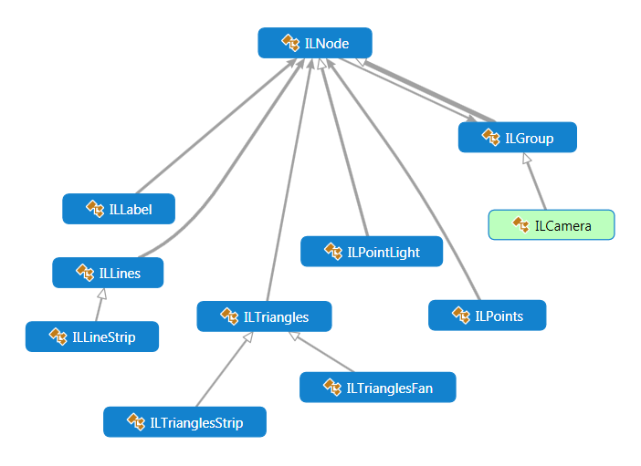
Every node in the scene graph is of a class type out of the following class hierarchy. Arrows in the image below indicate inheritance:

Basically, the only node types existing in a scene graph in ILNumerics are: labels, shapes (triangles, lines and points) and groups. All other objects are derived from group and compose those nodes to higher level nodes.
By only providing a very limited set of basic building blocks, ILNumerics is able to support a large number of rendering drivers like OpenGL, WebGL, Bitmaps, SVG, DirectX /XNA, PDF a.s.o., since they all have to support a very limited set of basic shapes only.
The absolute Minimum One needs to know about ILNumerics Visualization Engine:
- Everything that is supposed to be rendered and displayed is contained in a 'scene' (Scene).
- Scenes are abstract, i.e. not related to any specific rendering technology. They are created with a very expressive syntax, often by a single statement:
- Scenes are 3 dimensional: all objects are defined in a 3D space. Any 2D scene is actually a 3D scene, simply hiding the 3rd dimension.
- After creation, scenes are rendered by any of the available drivers. Each driver supports a specific technology: GDIDriver, OGLDriver (OpenGL), SVGDriver etc.
- Some drivers enable interactive capabilities: users can apply standard actions, as rotation, panning, zoom, and an unlimited number of custom interactive functions. Based on such scenes, dynamic, interactive GUIs are realized.
- Any scene object in a live scene can be changed - even in complex, costly ways. Call Configure() on the object to commit the change to the renderer for display afterwards.
- Use Panel, as available from the Visual Studio Toolbox! It wraps everything into an interactive Windows.Forms control.
Basic Scene Configuration
Regardless in which way you use a scene, its configuration will consist out of the following steps:
- Create a scene or access an existing scene.
- Configure the scene by adding objects / shapes to it, configure those objects in any way.
- Commit your configurations by calling Configure() on the changed part or the whole scene.
- Let a driver render your scene. For interactive drivers with Panel this is done automatically.
Default Interaction with Panel
In general, if not configured otherwise, the default mouse interaction on all scene objects in ILNumerics Visualization Engine works as follows:
Left mouse button: drag -> Rotation
Right mouse button: drag -> Pan
Mouse wheel -> Zoom In / out
Left Click -> Selection
Double Click -> Reset view
CTRL + Left button + drag -> Rotate around LookAt axis
SHIFT + drag -> fine adjust
ALT + drag -> restrict to horizontal or vertical direction
Interactive Web-Examples
Note, in the following documentation sections we will concentrate on creating scenes instead of windows. We will utilize the ILNumerics web components in the client browser. If a scene is created in a code area, it is converted to a visual image on the fly and immediately displayed. Try modifying the code and generate your own visualizations on demand!
Read more about visual code examples and the ILNumerics web component in the Web Examples How to. It also describes the few differences to apply when using scenes with other drivers.
